
Building a Robot Arm from Scratch
/ 4 min read
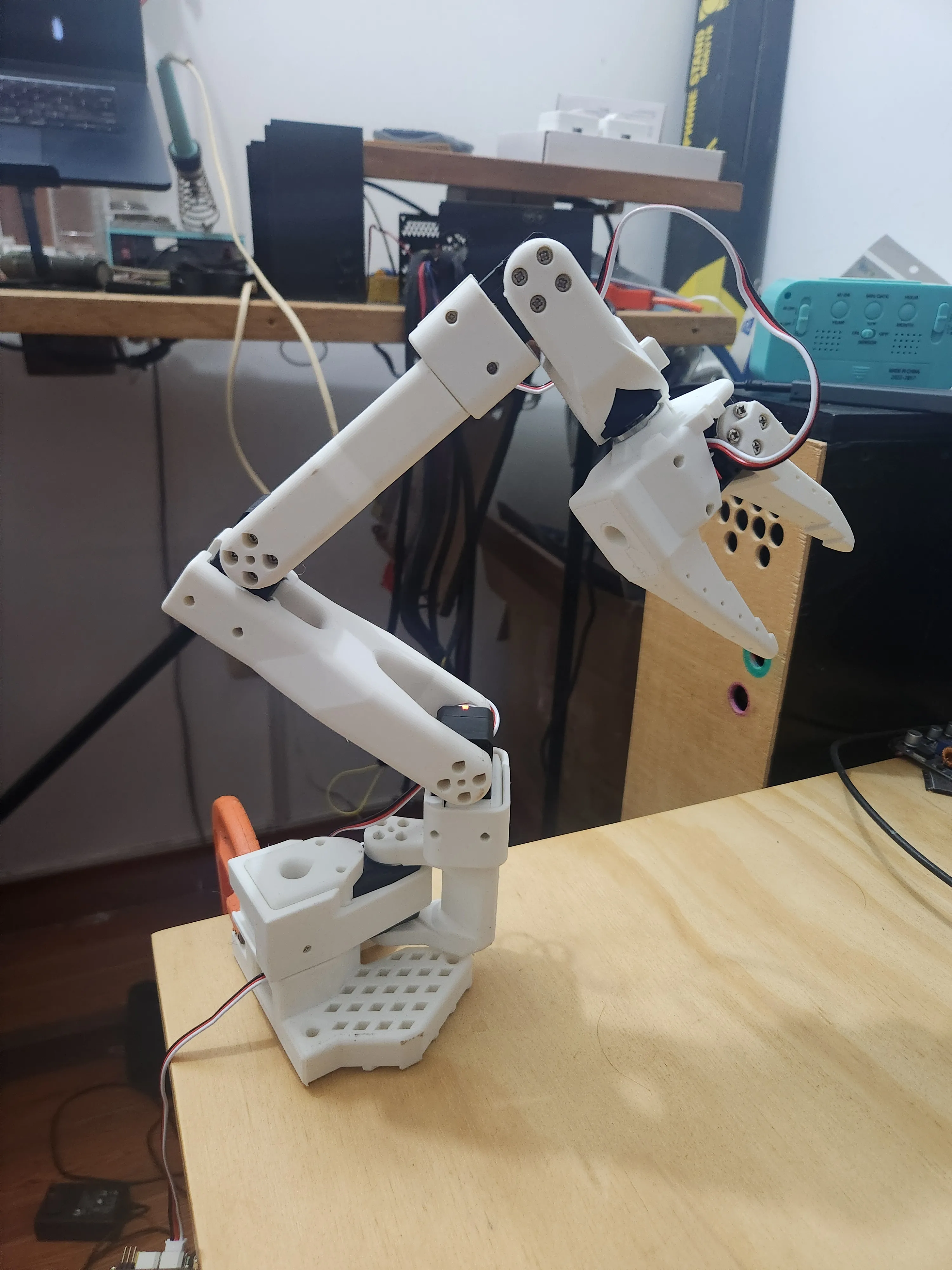
After the Machine Learning course in August, I wanted to build something to apply what I learned about computer vision and machine learning models. A robot arm seemed like a fun and challenging project that would let me explore both hardware and software aspects of robotics.
I found LeRobot’s STS3215 servo-based robot arm design online, which looked promising due to its affordability and ease of assembly. Over the next few weeks, I 3D-printed the parts, assembled the arm, wired up the servos, and developed a teleoperation interface using Python and MediaPipe for hand tracking.
How to start
There is a whole guide at LeRobot’s site, but since you are here, I will summarize the main steps:
- Gather parts: Download the STL files from LeRobot’s GitHub and source the STS3215 servos, power supply, and other electronics.
- 3D print the parts: Use a 3D printer to print all the necessary components. Make sure to use the recommended settings for best results. Put patience here, as printing can take several hours. For me it took more that 20 hours total. Some parts fail and need reprinting.
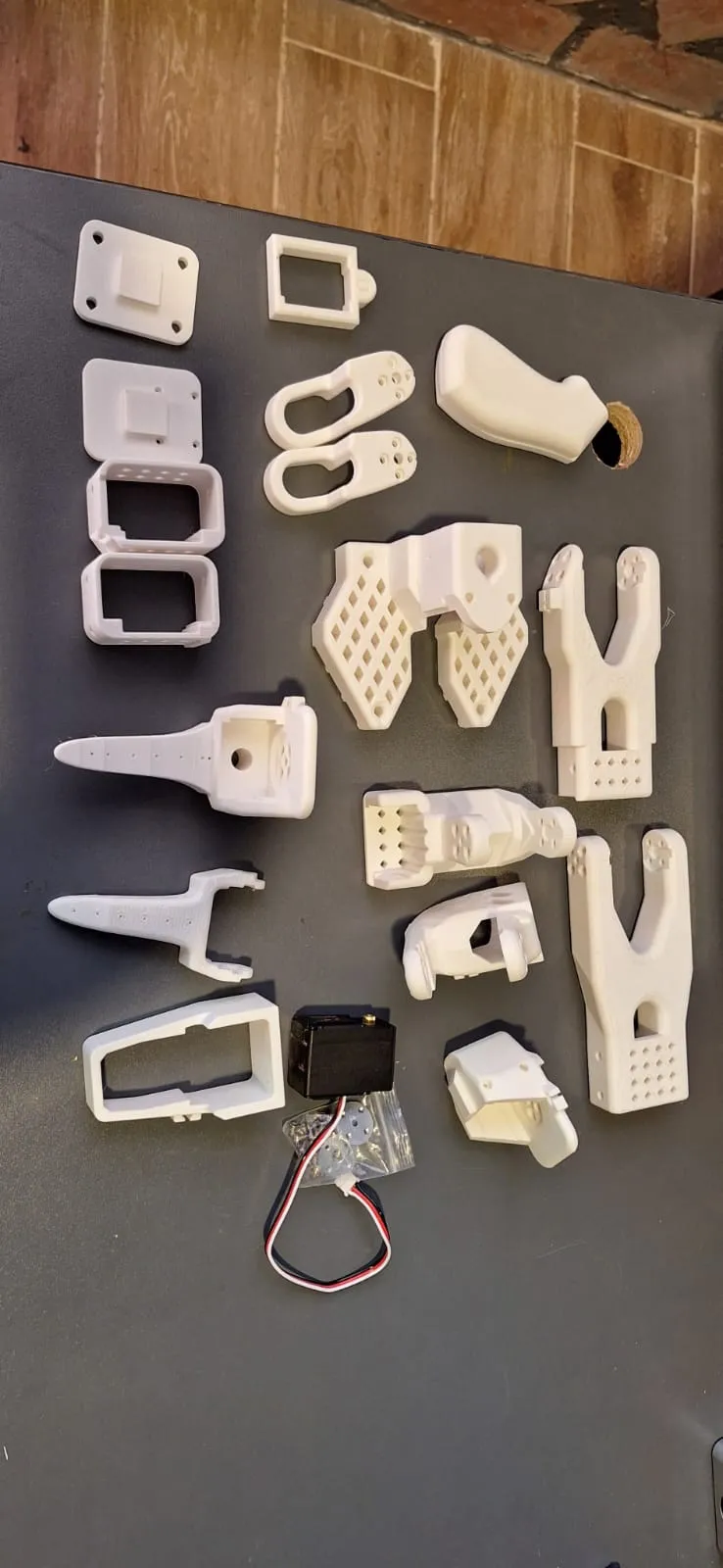
- Assemble the arm: Follow the assembly instructions carefully, ensuring all servos are correctly positioned and secured. Do not force the 3D-printed parts to avoid damage. I broke a few pieces during assembly and had to reprint them.
- Wire the electronics: Connect the servos to the microcontroller, ensuring proper power and signal connections. The servos can draw a lot of current, so use a suitable power supply.
- Configure the servos: Set an id for each servo and test their movement using simple scripts. There also some scripts provided by LeRobot to help with this.
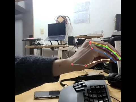
- Develop the teleoperation interface: Use Python and MediaPipe to create a hand-tracking interface that maps your hand movements to the robot arm’s servos. This part can be tricky, as you need to calibrate the mapping and ensure smooth operation. However, I think this is also implemented somewhere else online.
- Keep iterating: Test the arm’s movements, make adjustments to the code and hardware as needed, and refine the teleoperation experience. This will take forever, so be patient and enjoy the process! Mine is still a work in progress.
Start printing
The guide in LeRobot’s site is very detailed, so I will not repeat everything here. Instead, I will share some photos and videos of my build process and highlight some challenges I faced along the way.
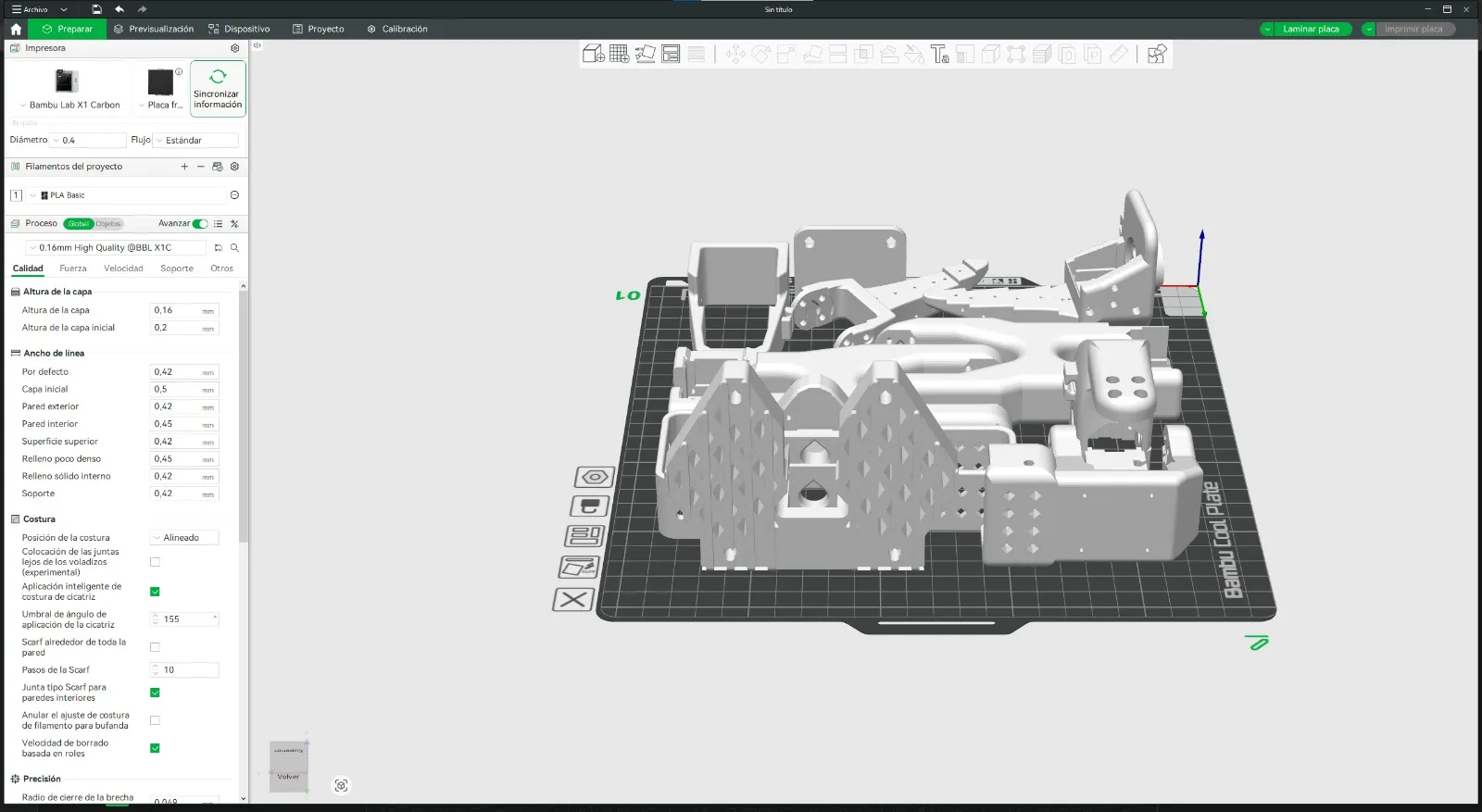 In my experience if I print everything at once like in the picture above, some parts will fail due to warping or adhesion issues. I recommend printing smaller batches and checking each part before moving on. In my case I printed almost every part separately, and made the layers thicker to reduce the chance of failure. Specially for the bigger parts like the base and the arm segments, it takes a lot of time.
By the way, I used PLA-CF filament for this project, which is easy to print but not very strong. Still, pretty strong for this application. Some pieces broke during assembly, so I had to reprint them. Especially the small servo mounts. So, be careful when assembling the arm. Other pieces failed when printing them because I left and 1 hour later they had moved or warped. So, better to do a small baset first and see if everything is working fine, and apply glue or tape to the bed if needed.
In my experience if I print everything at once like in the picture above, some parts will fail due to warping or adhesion issues. I recommend printing smaller batches and checking each part before moving on. In my case I printed almost every part separately, and made the layers thicker to reduce the chance of failure. Specially for the bigger parts like the base and the arm segments, it takes a lot of time.
By the way, I used PLA-CF filament for this project, which is easy to print but not very strong. Still, pretty strong for this application. Some pieces broke during assembly, so I had to reprint them. Especially the small servo mounts. So, be careful when assembling the arm. Other pieces failed when printing them because I left and 1 hour later they had moved or warped. So, better to do a small baset first and see if everything is working fine, and apply glue or tape to the bed if needed.
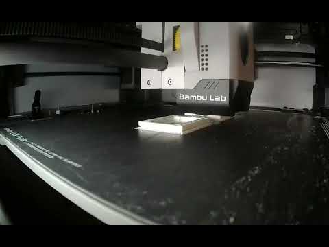
Watch the start of the printing process:
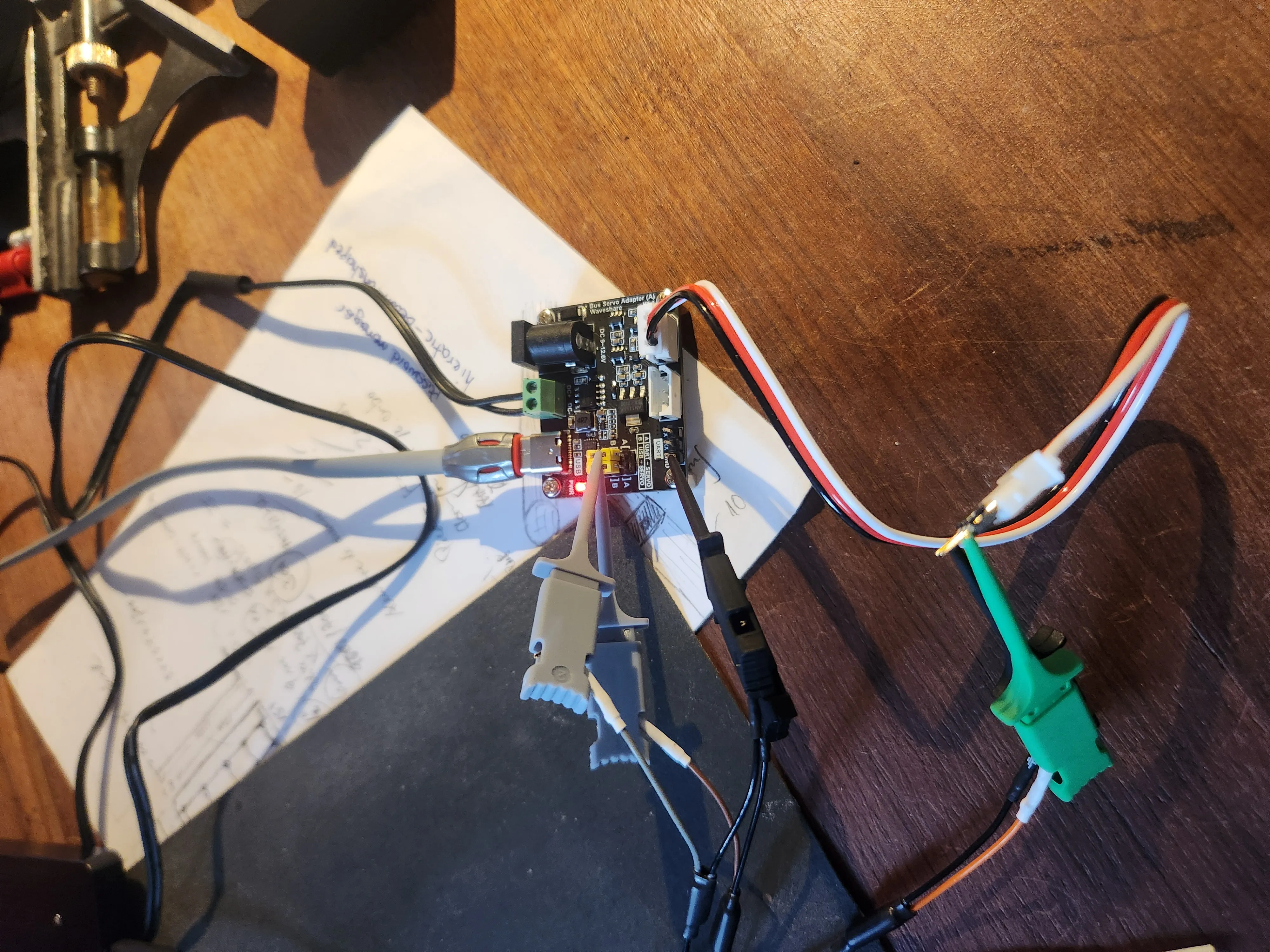
Troubleshooting the driver
During the build, I was having some trouble with reading, and writing the servos. So, I used a logic analyzer to check what was going on. My commands were the issue, so just an exercise in the end.
Teleoperating the arm
Status
more detail and images coming.